
Supersonic
Wind Tunnel
May 2020 - May 2021
Motivation
Pursuing my interest in aerodynamics and the challenge of advanced fluid dynamics, I designed and built a supersonic wind tunnel achieving Mach 1.8 in the test section.
Project Overview
Problem:
Design a supersonic wind tunnel capable of supersonic flow (Mach 1.8) in the test section.
Action:
-
Learn and understand the intricacies of supersonic flow
-
Calculate values for pressure, area, and Mach number throughout the tunnel
-
Model wind tunnel in Solidworks and analyze flow with ANSYS
-
Research materials
-
Manufacture and test tunnel
Result:
The final deliverable for this project is a physical wind tunnel that will be used in NEU's labs. After testing (on Monday, April 19th, 2021), the tunnel proved to be a success!

Technical Challenges
Pressure Drop
A significant pressure drop must be induced in order to achieve supersonic flow. All calculations will be informed by this decision, our desired Mach number, and the flow and shock relations.
At supersonic speeds, the flow's behavior changes. Thermodynamic properties such as density, temperature, and pressure change significantly. This must be reflected in the calculations. The calculations must take advantage of these relationships to achieve supersonic speeds.
Once built, the system will run on a vacuum. Since the pressure will be crucial to achieving supersonic flow, all parts and components must be airtight. We needed to mitigate opportunity for leaks in every part of our design.
Airtight Design
Identifying the Profile
Actions:
Problem Statement
Identifying the Problem
For my senior capstone project, I am designed a lab desk-top-sized Supersonic Wind Tunnel for use in Northeastern University's Intro to Flight course. The tunnel must achieve Mach 1.8 in the test section, demonstrate flow over an airfoil, and be easily operated by students.
1. Learning Compressible Flow
Learning the basics
In order to approach the problem, we first needed to study how air behaves at that speed, My team and I spent the first few weeks reading John D. Anderson's Modern Compressible Flow textbook and attending an accompanying lecture presented by our advisor Dr. Medhi Abedi. I explored the intricacies of high-speed flow and was interested to learn that at supersonic speeds air velocity has an inverse relationship with the tunnel's cross-sectional area. This means that the air will speed up as the cross-sectional area decreases!

Figure 1: Cover of Modern Compressible Flow by John D. Anderson
2. Calculations
I calculated the initial tunnel profile using my understanding of compressible flow and isentropic relationships. To take advantage of the area-velocity relationship in supersonic flow, I used a converging-diverging nozzle design. I used the following equations to calculate the pressure, temperature, density, and area at the Inlet, throat, and test sections.
Assumptions:
-
Atmospheric conditions at the inlet
-
Inviscid, compressible, isentropic
-
Steady, fully developed
-
Quasi-one-dimensional
Knowns
-
Mach 1.8 in Test Section
-
Choked flow at throat
Validated in ANSYS

Nozzle
Figure 2: Nozzle Profile
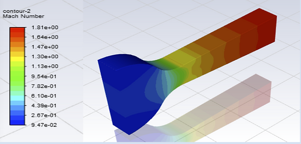
Figure 3: Nozzle Mach
Diffuser
Assumptions
-
same as nozzle
-
shock is non-isentropic
Knowns
-
same as nozzle
Options
-
Exhaust from test section
-
second CD Nozzle
-
diffuser only
These values were obtained through pressure relations I learned in Chapters 3, 4, & 5 of the testbook. Applying these to Tables A.1 and A.2 in the back allowed me to obtain the appropriate values for my windtunnel.

Isentropic Relations

Figure 4: General Schematic of a Supersonic Windtunnel from Modern Compressible Flow
3. ANSYS Simulations
In order to confirm our calculations, we ran ANSYS simulations on a 3D model of our test section. We obtained plots of the Mach number and pressure distribution.


4. Volumetric Flow Rate & Power

Based on these calculations, we decided to use a vacuum system rather than a compressor. We purchased an RX-202 Blower from Republic Manufacturing (link to spec sheet).
5. Test Section Design
Requirements
1. Must be able to visualize the flow
2. No flow disturbances
3. Access to Airfoil
Since we were using a Schlieren imaging system, the test tunnel's test section needed to be transparent. Additionally, to void flow disturbances the design needed and air tight seal with no points protruding into the flow. I brainstormed a few designs seen below.


This was the final design.

Features
1. Acrylic walls
2. gasket seal
3. 6 M4 bolts
Calculations & Validation
Walls
Gaskets

Bolts

6. SolidWorks Models
Figure 5 & 6 depicts the Solidworks model of our wind tunnel (made by Daniel Trapp). These images the wind tunnel design. It will reach Mach 1 at the throat before speeding up via the divergent section to reach Mach 1.8 in the test section. The flow will then be slowed down via normal shock induced by the second converging-diverging nozzle.


Figure 4: Tunnel subassembly
Figure 5: Full tunnel Assembly


Assembly & Testing

Tunnel components pre-assembly
Schlieren Photography
The purpose of this tunnel is to analyze flow around different airfoils traveling at supersonic speeds. In order to visualize what is happening in our test section, we needed to utilize a special type of imaging: Schlieren photography.
Schlieren Photography is an imaging method that utilizes the deflection of light due to a refractive index gradient to depict flow patterns. The refractive index gradient is directly related to the flow density gradient. As density increases, less light will travel through it. Although not perceivable to the naked eye, this contrast is visible with schlieren photography. This precision of the camera illustrates the variable density via a light gradient.
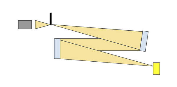
Diagram of Schlieren Photography set-up
The Schlieren imaging kit was among the first pieces to arrive. Using trigonometry, we estimated the location of each component. From there we adjusted the individual angles until we could visualize the flow thorough the camera.
Shlieren Imaging Set up
Testing Cast acrylic walls for obstruction

Schlieren Image of a Candle
Results
On Monday, April 19th, my team and I tested our windtunnel! The project was a success: we achieved supersonic flow in over they airfoil and visualized the shocks via Schlieren photography. Blow you can see a video captured through the Schlieren setup and a picture used for analysis.


Team Picture in front of the working tunnel
Schlieren video of successful wind tunnel test!

Schlieren Image of test section with Supersonic Flow